

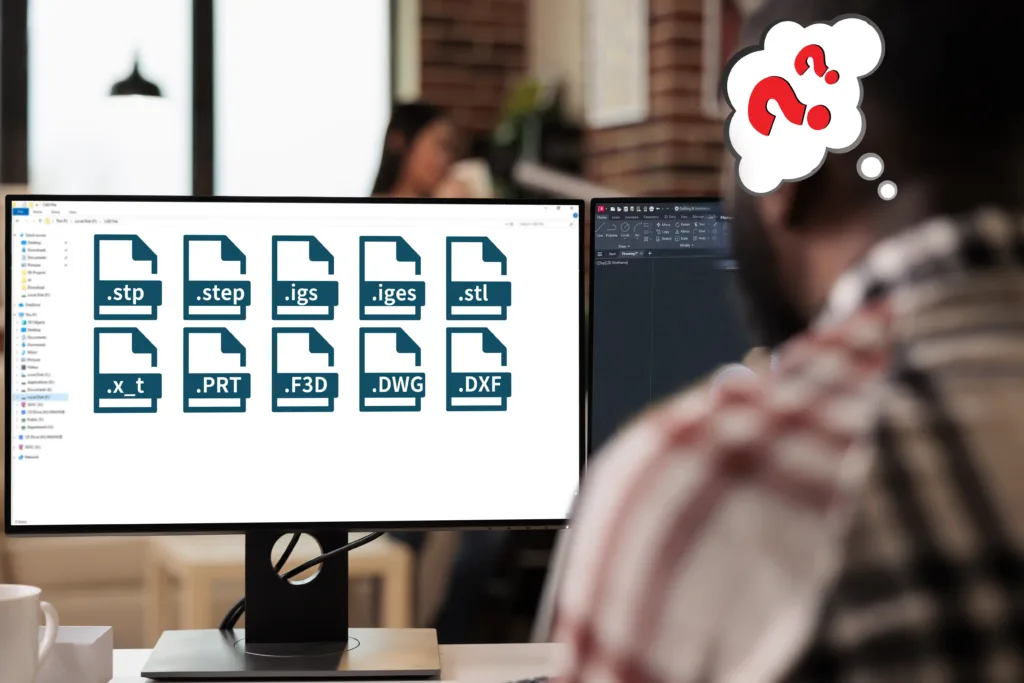
How many times has this happened to you? You send a part for an enquiry, then the manufacturer replies: “Can you share it as STEP?”
That one extra email seems minor, but it often turns into a delay while someone re-exports files, fixes missing solid geometry, or clarifies what the model actually represents.
This usually happens when the file format isn’t up to date or isn’t the ideal match for the process that’s going to be used to make it. For example, an STL might be easy to share, but actually that file format is only used for stereolithography. Compare that with CNC machining, where most shops need a solid CAD file (like STEP) to generate toolpaths and review geometry properly.
Below, we’ll show the best formats to use when preparing for CNC machining, injection molding (PIM), and laser cutting – so you can send a faster, cleaner enquiry the first time.
1. How File Formats Connect Design and Manufacturing
For CNC machining, your CAD files are fed into CAM (computer aided manufacturing) software that converts the geometrical information of your design into toolpaths – how the cutters move to shape your part.
With injection molding, the CAD model dictates the manufacturing of the mold tool rather than the finished piece. In either case, every CAD file format contains different types of information that can be interpreted in different ways.
That why it’s so important to send the right type of file format, so we can program the machines correctly while still preserving your design intent.
2. CAD File Formats at a Glance
Here’s a quick reference table we share with clients before they upload their files. Bookmark it, you’ll use it more often than you think.
| File Type | Extension | Data Type | Best For | Key Features / Notes |
|---|---|---|---|---|
| STEP | .stp, .step | Solid geometry (neutral) | CNC machining, plastic injection molding | Universal, accurate, & stable for most production jobs. |
| IGES | .igs, .iges | Surface geometry (neutral) | Legacy CAD systems | Good backup when STEP fails but can lose volume info. |
| STL | .stl | Mesh (triangulated) | 3D printing | No geometry data. Not ideal for machining or molding. |
| Parasolid | .x_t, .x_b | Solid geometry | CNC machining | Accurate & compact; for complex machined parts. |
| Native CAD | .SLDPRT, .CATPart, .PRT, .F3D | Fully parametric | Design revisions or collaboration | Great for design, but not always readable by other systems. |
| 2D Drawing | .DWG, .DXF | Vector lines | Laser cutting, flat parts, | Often used alongside 3D files for secondary ops or inspection. |
3. Understanding Data Types
Notice in the chart there are different data types, so let’s take a look at what that means.
Solid geometry (neutral)
A solid geometry is the final shape of the part, basically a collection of surfaces and solids that don’t reference the underlying constraints or parameters that created them. Solid geometries need to be ‘watertight’, with no gaps or broken lines. A watertight drawing is said to have volume.
A neutral file format, like STEP, is platform-independent and works almost anywhere. Note that there’s no feature history, so any change in the data (let’s say, altering a dimension or moving the location of a hole) means making a new CAD file.
Surface models
IGES is an older CAD file format that represents surfaces as a series of mathematical lines, curves, and boundaries. There isn’t an implied “inside” or “outside”, it’s just a skin with no interior volume.
Because the final shape is stitched together from separate pieces, it’s easy to lose watertightness with this format or have overlapping features. Unfortunately, it’s also possible that some features can be interpolated into their mirror opposites, causing CNC machining errors. This means IGES data files typically take longer to troubleshoot and prepare for manufacturing.
Mesh (triangulated)
Shapes are formed from a collection of connected polygons, usually triangles. There are no continuous lines or curves and no volume information, so the final shape is an approximation. The surface quality can be visually improved with higher resolutions (more polygons), but this also increases the file size.
This file format is definitely not suitable for high precision manufacturing, but it’s ideal for 3D printing.
Fully parametric
This is the most information-rich format. It’s based on parameters, constraints, and a history tree. Every feature is defined by rules and dimensions, and if any of these parameters are changed then the entire program automatically updates to reflect the new data, like an Excel spreadsheet.
Importantly, this CAD file format saves its history. That makes it easy to see how a feature evolved over time into its final form. This is a great help for the manufacturer, who can clearly understand the design intent while fine-tuning the parameters. It does however require more sophisticated CAM software to interpret.
Vector lines
Lines show the product profile, contours, and features in 2D, which is used by CAM systems to generate tool paths. DWG is native to AutoCAD, while DXF is universal and can be read by most systems.
Because there is no direct 3D data, these CAD file formats are best used for waterjet or laser cutting of sheet metal and other flat stock.
If you’re ever unsure, send a STEP file. It’s the most widely accepted and plays nicely with nearly every modern CAD/CAM platform.
Book A Discovery Call
Not ready for a quote? No worries, book a quick call with the sales rep in your area.
4. Why You Still Need To Provide PDFs – The “Human” Side of the Job
For most jobs, providing a clean drawing in STEP format along with a 2D PDF drawing is the fastest way to generate a quotation and get started.
PDFs are great because they help both you and the manufacturer document a project and track any revisions. You can also add important information to explain what the part is for, not just how to make it. Well-organized PDFs include:
- Part name and revision number
- Dimensions and tolerances
- Surface finish and flatness
- Color
- Material notes and special requirements
We use the CAD file for geometry and the drawing file to double-check everything just to be sure.
5. Matching File Type To The Manufacturing Process
We know this is a lot of information so let’s make it as clear and simple as possible. For all conventional machining and molding operations, your best bet – fastest, easiest, bulletproof, universally accepted – is to upload a STEP file along with 2D PDF. That’s it.
STEP files are watertight, can be read by virtually any system, and contain all the information that your supplier needs to make your parts without any possibility of miscommunication. It’s the way to go.
| WHAT ARE YOU SENDING? | BEST FORMAT | OK FORMAT | BAD FORMAT |
|---|---|---|---|
| Plastic part model | STEP (.stp, .step) | Parasolid, Native CAD | STL |
| CNC machined parts | STEP (.stp, .step) | Parasolid, Native CAD, IGES | STL |
| Mold/tool design | STEP (.stp, .step) | Native CAD, Parasolid | STL |
| 2D flat part (laser) | DXF / DWG | STEP | |
| 3D print prototype | STL | STEP | IGES |
CNC Machining
CNC machines thrive on precision, and achieving that requires solid, watertight drawing files. Mesh or surface-only files simply don’t work here.
Avoid: STL, IGES (surface only), or DXF. They lack the solid-body data needed for reliable toolpaths.
Plastic Injection Molding
Mold tool designs prioritize important features like draft, wall thickness, and surface transitions. That’s why mold makers need 3D solids, not mesh files. With a solid CAD file they can get started right away on designing for cavities and parting lines without needing to rebuild geometry.
Avoid: STL or 2D DXF. They won’t carry the 3D geometry or wall data your mold maker needs.
3D Rapid Prototyping
This is where the STL format finally shines. For 3D printing, you don’t need parametric or solid-body data; you just need a clean surface mesh.
Watch out: STL files don’t store units. You must always specify whether your model is in inches or millimeters.
Sheet Metal, Laser Cutting, and Secondary Operations
If your design includes flat profiles, patterns, or hole locations, you’ll often need a 2D vector file.
The Quick Takeaway
If you’re ever unsure, send a STEP file. It’s the most universal format out there – solid geometry, widely compatible, and perfect for both precision CNC machining and plastic injection molding.
6. Save Time By Using The Right File Type
Not so long ago we had a client send us a housing design for a prototype and they wanted it CNC machined from aluminum. No problem there, but the CAD file was in STL format. If you load this kind of file into the CAM software, what you come out with is a watertight solid object with a multifaceted surface. There won’t be any arcs or straight lines, just a series of stair-steps.
It’s impossible to be precise with this kind of file, so we had to ask the client to reprogram the drawing in STEP format. A very fixable problem of course, but no product designer wants to waste time and resources like this when it’s so much easier and more efficient to just get it right the first time.
7. Tips for Sending Files Like a Pro
You don’t need to be a machinist to make life easier for your manufacturer. Just follow these best practices. They may seem obvious, but you’d be surprised how often they’re overlooked.
- Name files clearly. Use part name + revision, e.g., Handle_revC.step.
- Zip assemblies. Keeps everything organized and prevents missing references.
- Check units and tolerance callouts. Avoid confusion between metric and imperial. When using GD&T, specify the revision number.
- Run a geometry check. Many CAD programs have “repair” tools to fix open edges.
- Include a PDF drawing. It’s your insurance policy for clarity.
Those five minutes of prep can shave days off your production time.
8. How Procision Manufacturing Helps You Get It Right
At Procision, we’ve built our workflow around clarity and speed. Our engineers can handle just about any CAD file format you can throw at us, including STEP, IGES, Parasolid, SolidWorks, Fusion 360 – you name it.
If something doesn’t come through cleanly, we’ll repair or convert it in-house before quoting. And if you’re not sure which format to use, just BOOK A DISCOVERY CALL now!
Whether you need high tolerance CNC machining or precision plastic injection molding, we’ll help you move from design to finished part without the guesswork.
9. Project Checklist
Choosing the right CAD file format isn’t just a technical detail. It’s a time-saver, a cost-saver, and sometimes a project-saver.
- Use STEP for machining and molding.
- Use STL for 3D printing.
- Always send a PDF for the humans in the loop.
That simple checklist keeps your project flowing smoothly, from CAD to CAM to finished part.
We’ve helped countless designers streamline this process, and we’d love to help you do the same.
")


