

Whether you’re designing an aerospace component, automotive assembly, or handheld medical device, CNC-machined threads play an important role in your product’s success. Poorly made threads can delay production, cause costly rework, and compromise performance and they often fail for reasons that aren’t obvious until it’s too late.
This guide can help engineers to choose, specify, and apply the right thread types so you can avoid preventable issues, hit your timelines, and deliver parts that perform as intended.
Understanding the Importance of CNC-machined threads
Threads have been used for centuries, but their engineering has never been more relevant. Modern CNC machined products, from surgical robots to wind turbines, depend on precisely made threaded fasteners and fittings to assemble, align, lock, and adjust components.
Because they’re common, they often get overlooked in the design phase. But that’s a mistake:
- A misplaced or poorly specified thread can scrap an otherwise perfect part.
- The wrong profile or pitch can compromise load capacity, resistance to vibration, or service life. Pitch, or the distance between threads, is critical when selecting the correct screw or bolt and ensures proper fit and function in assemblies.
- Incomplete specifications can confuse suppliers and stall production.
By understanding the functions, classifications, and manufacturing methods of cnc-machined threads, you can build designs that assemble easily, perform reliably, and pass first article inspection without drama.
Examples of Threaded Fittings and Fasteners
Assembly / disassembly
Alignment and positioning
Converting axial rotation to linear motion
Strengthening / reinforcement
Dissipating mechanical stress
Allowing access to internal features
Calibration / tuning
Locking / unlocking
Here are just a few examples of use cases that we all rely on every day.
1. Assembly / disassembly
Example: Engine cases, mounting brackets, appliances
2. Alignment and positioning
Example: Telescope mounts, leveling screws
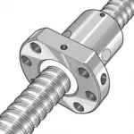
3. Converting axial rotation to linear motion
Example: Ball leadscrews, machine tool vices
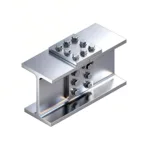
4. Strengthening / reinforcement
Example: Structural plates, locking clamps
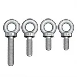
5. Dissipating mechanical stress
Example: High vibration assemblies, eye bolts
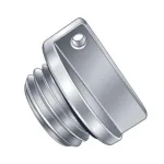
6. Allowing access to internal features
Example: Maintenance covers, oil reservoirs, viewports
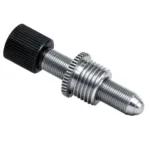
7. Calibration / tuning
Example: Guitar string tuning posts
8. Locking / unlocking
Example: Shut-off valves, mechanical deadbolts
Ready to machine CNC threads with confidence?
Upload your drawings for a free quotation from Procision Manufacturing.
What Are CNC-machined threads?
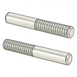
Let’s define our terms for clarity. CNC-machined threads are helical, spiral grooves applied either into the surface of a cylindrical hole (internal / female), or the outside of a circular or conical shaft (external / male).
Bolts, screws and studs are external, while nuts and receiving holes are internal.
Cutting threads is a common method for creating both internal and external threads, and using proper techniques and tooling is essential for achieving accurate and efficient results.
What’s the Purpose of machine screw threads?
The most common purpose is to act as an interface for a corresponding fastener. The mechanical linkage between the two interlocking helixes helps to hold parts together under tension.
Specifying the desired thread, including its pitch and dimensions, is essential for ensuring proper fit and function in fastening applications.
CNC-machined threads, and the attachment hardware linked to them, can also convert axial rotation to linear movement, such as with leadscrews or adjustable table legs. They also help distribute mechanical loads.
What’s the Importance of Spring Tension?
For nuts, bolts and screws, the head of the fastener pulls against the resistance of the helical flutes. This creates spring tension in proportion to the geometry of the thread and its engagement length.
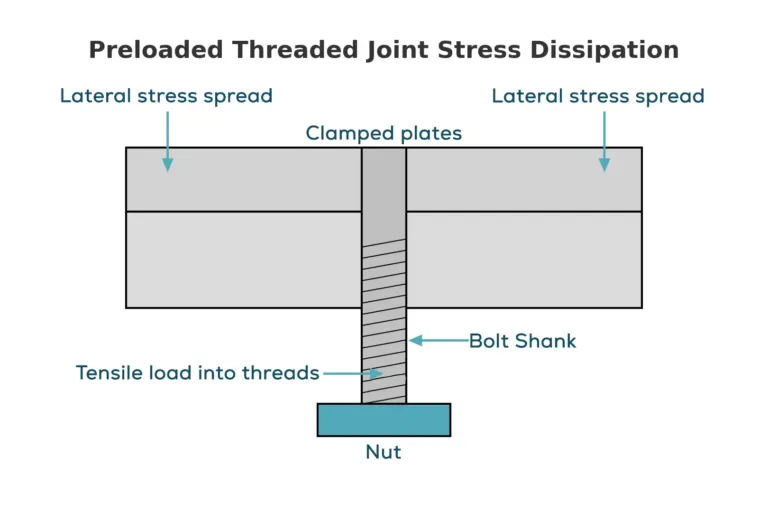
It’s this tension that dissipates force through the surrounding material and holds the assembly together.
Even if a bolt or screw head is sheared off, the threads will still remain under dynamic tension.
Thread Terminology
We don’t want to be too technical here, because entire engineering textbooks have already been written on this subject. Instead, we’ll focus on the basic parameters that are used in most reference systems.
Threads are defined by various diameters, including the major (external) and minor (internal) diameters, which are critical for proper thread formation and ensuring the correct fit and strength of both external and internal threads.
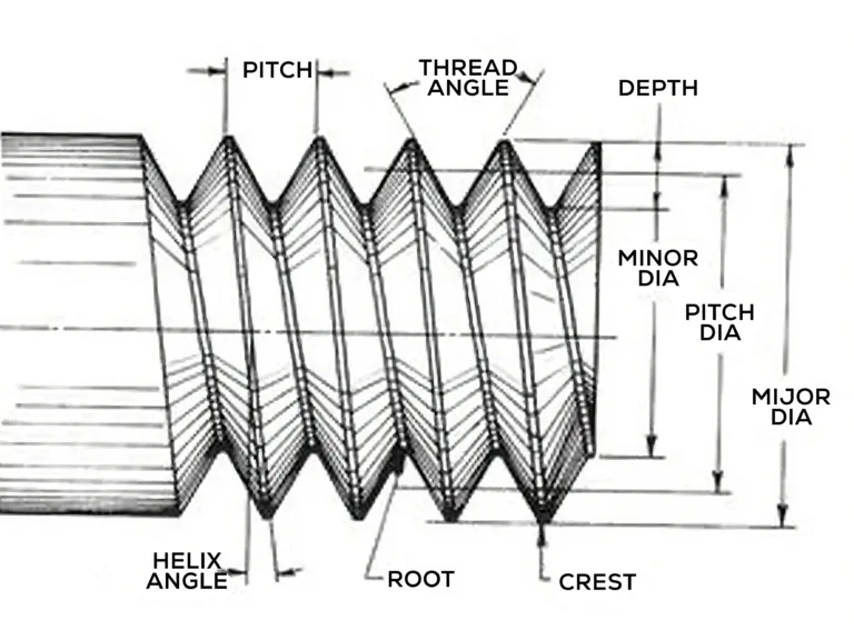
Thread depth
Thread depth determines how deep the groove is cut. For CNC machine programming, the cutting depth is a key parameter, specified as a G76 command.
Major diameter
The major diameter is the maximum thread size, measured either at the peak for external threads or the valley for internal. This value is used in all international systems.
It’s important to verify the workpiece diameter to ensure it meets specifications, as this directly affects achieving precise thread dimensions and overall performance.
Pitch
The number of threads per inch (TPI for imperial measurement), or the distance between two adjacent thread peaks in millimeters (ISO / metric). The number of threads in a given length defines how fine or coarse it is.
Larger pitches require special considerations during thread machining, as the increased distance between thread peaks can lead to greater vibration and a higher potential for chatter.
Profile
The shape of the thread from a side view. Threads can be v-shaped, square, rounded, trapezoidal, or asymmetrical. Each of these shapes serves a special purpose to suit the application.
Helix angle
The helix angle is the angle formed between the thread’s helix and its axis. It plays a key role in thread design, especially for taper and multi-start threads, as it affects how the threads engage and transmit force. The helix angle is also important when selecting shims and designing thread profiles to ensure proper fit and function. Most angles are between 55° and 60°.
Handedness
The vast majority of CNC machined threads and fasteners are right hand threads, meaning they tighten in a clockwise direction. Right hand threads are standard in most general applications due to their prevalence and ease of use. However, some threads are left-handed for security reasons or to suit the application (e.g., the left side of a bicycle crank arm).
Classification Systems
Each classification system defines specific machine screw thread forms and standards for manufacturing and inspection. Metric threads are widely used in global applications and are part of the ISO standard system.
Standard threads, such as those defined by ISO, ASME, and other bodies, ensure compatibility and ease of manufacturing. When you’re calling out thread dimensions on design drawings, always specify which classification system you’re using to avoid any potential confusion with your manufacturing partner.
Comparative Reference Table — Thread Classification Systems
| System | Thread Profile | Typical Use Cases | Common Variants | Example Designation | Standard Body / Spec |
|---|---|---|---|---|---|
| ISO Metric Thread (ISO 68-1, ISO 261, ISO 965) | 60° symmetrical V-thread | General-purpose fasteners, global standard | Coarse, fine, extra-fine | M12 × 1.25 | ISO |
| Unified Thread Standard (UTS / UN) (ASME B1.1) | 60° V-thread, rounded crest & root | North America general-purpose fasteners | UNC (coarse), UNF (fine), UNEF (extra-fine) | 1/4-20 UNC | ASME, ANSI |
| British Standard Whitworth (BSW / BSF / BSP) | 55° rounded thread | Legacy British machinery, pipe fittings | BSW (coarse), BSF (fine), BSPT/BSPP (pipe) | 1/2” BSPT | BSI |
| National Pipe Thread (NPT / NPTF / NPS) | 60° taper (NPT/NPTF) or straight (NPS) | U.S. pipe fittings | NPT, NPTF, NPS | 1/2-14 NPT | ANSI/ASME, SAE |
| Trapezoidal / ACME | ACME: 29° trapezoidal; ISO trapezoidal: 30° | Linear motion, leadscrews, power transmission | Stub ACME, multi-start | 3/4-6 ACME | ASME, ISO |
| Buttress | Asymmetric: one vertical flank, one angled (~45°) | High-load in one direction | N/A | Custom spec per application | DIN, various |
Upload your drwaings to get a faster manufacturing quotation for your CNC machining projects.
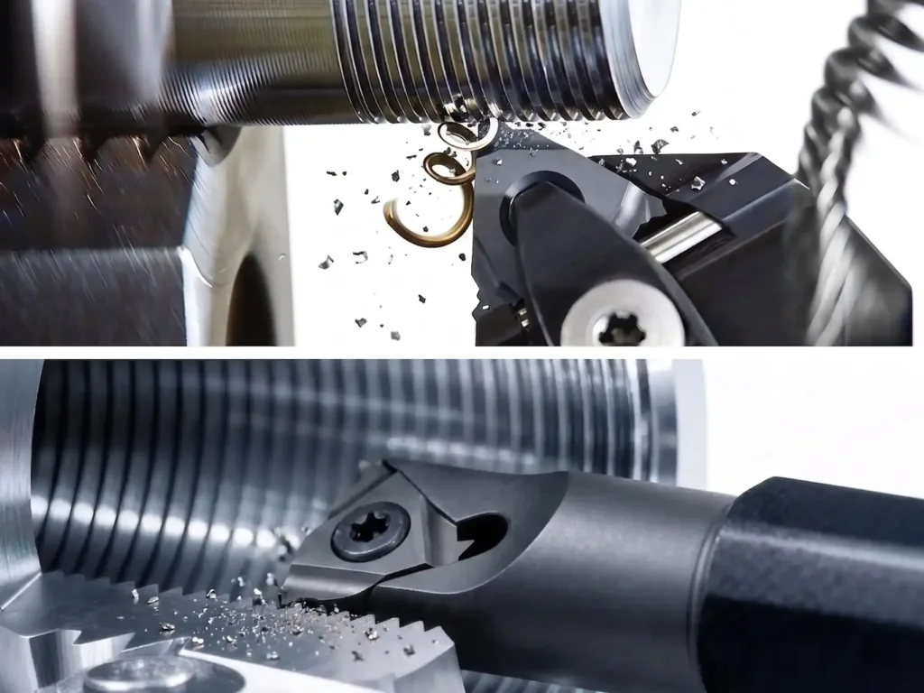
CNC Machining Methods
The way a CNC-machined thread is produced has a lot to do with its performance. Thread machining is the collective term for the various CNC thread cutting processes, each offering different advantages in terms of precision, efficiency, and application.
Not all threads are the same and each CNC machining process, whether it involves cutting, rolling or grinding, has trade-offs in cost, precision, and production lead time.
Thread turning is typically performed on a CNC turning center, which is capable of producing many different thread profiles depending on the tool used. The entire manufacturing process, from the initial programming and setup to final inspection, must be supervised by skilled and experienced machinists to guarantee consistent results.
CNC machine programming using G-code often refers to a G76 command for cutting thread grooves. Careful programming plays a significant role in determining the efficiency and precision of the lathe threading operation.
Selecting the right cutting speed and feed rate is essential for optimal thread quality, tool performance, and to prevent issues like overheating or tool failure. Effective chip control is also important. Techniques like modified flank infeed, the use of precision coolant, and advanced tool profile design help manage chip evacuation, improve machining efficiency, and ensure consistent thread quality.
Choosing the appropriate insert types and turning tool for the application is crucial, as different nose radii and tool geometries influence performance and machining security.
Most rigid materials can be threaded, although some metals are hard to machine and this can negatively impact tool life.
For all of these above reasons, it’s always best to discuss your specific needs in advance with the manufacturer to ensure you’ve chosen the right thread type and material for your application.
CNC Thread Manufacturing Methods — Comparative Reference Table
| Method | Applies To | Process Type | Advantages | Limitations | Best For |
|---|---|---|---|---|---|
| Thread Milling | Internal & External | Material removal (cutting) | High precision; works on hard materials; can cut anywhere on a part (not just ends); supports custom profiles; works for deep or blind holes | Slower than rolling; higher tooling cost; more setup time | Complex geometries, small-to-medium batches, prototypes |
| Thread Rolling | External only | Cold forming (material displacement) | Superior strength & surface finish; no material waste; high repeatability; very fast at volume | Requires dedicated rolling dies; limited to ductile materials; initial die cost | High-volume production of standard profiles |
| Die Threading / Thread Cutting | External only | Material removal (cutting) | Low cost; fast for identical parts; simple tooling | Less precise than milling or rolling; limited durability of dies; cannot handle very hard materials | Low-to-medium volume, general-purpose external threads |
| Drill Tapping | Internal only | Combination drill + tap (cutting) | Fast; ensures perfect pilot-to-thread alignment; ideal for CNC batch work | Tool wear is high; less suited for deep holes | High-volume production where speed is priority |
| Thread Tapping | Internal only | Material removal (cutting) | Simple, low-cost tooling; good for many materials | Limited chip clearance; not ideal for deep or blind holes; lower precision | General-purpose internal threads in low-to-medium volumes |
| Self-Tapping Screws | Internal (via fastener) | Cutting during assembly | Eliminates pre-threading step; low tooling cost | Low precision; not for critical applications; risk of material damage | Sheet metal, plastics, non-critical fastening |
| Thread Grinding | Internal & External | Abrasive material removal (grinding) | Extremely high precision and surface finish; ideal for hardened materials; can achieve tight tolerances and fine pitch accuracy | Slower process; higher equipment and tooling cost; requires specialized setup | Critical applications requiring ultra-precise threads, hardened steels, aerospace and medical components |
External Threads
External threading is the process of CNC cutting threads on the outer surface of a workpiece, which is essential for creating strong and reliable mechanical assemblies.
When designing external threads, it is important to specify the correct thread diameter to ensure proper fit and function of the connection. There are four main processes for making external threads.
1. CNC Thread milling
Thread milling uses a single pointed bit mounted in a tool holder to cut the threads. On a CNC turning center, the bit is held stationary while the workpiece is rotated. On a CNC milling center, it’s the workpiece that’s held stationary.
This can be a real advantage if there’s a threaded feature you want to put on a part that otherwise can’t be turned on a lathe.
Milling works with both male and female threads, and is a good choice for hard-to-machine super alloys or titanium(super alloy milling or titanium milling). However, the operator needs to carefully control cutting speeds and feed rates.
Another advantage to milling is that it can make threads on non-cylindrical (e.g., conical) stock. Perhaps most importantly, the tool can make a thread anywhere it’s needed. It’s not limited to working from just one end, which opens up many more design possibilities while avoiding costly set-ups.
Together, these qualities make thread milling the most versatile method used on multi axis CNC turning centers and Swiss-type lathes such as we have at Procision.
2. Thread rolling
Thread rolling uses a hardened steel die pressed against the workpiece to form threads by displacement rather than cutting. This results in a superior thread form with better surface finish, higher tolerances, and greater mechanical strength. There’s also no material waste.
Thread rolling only works on ductile metals and it requires a specialized machine using standard forming tools. It excels at high volume production of machine threads for general use.
3. Die threading / thread cutting
A one or two-piece circular die of a given diameter shears material away as it’s simultaneously pressed and rotated onto the end of the shaft. The first cut made by the die sets the foundation for subsequent passes and is critical for achieving thread accuracy.
Dies aren’t especially precise but they’re fine for high volumes of general-purpose threaded parts to achieve the lowest cost and fastest throughput.
Internal threads
Internal threading can only be applied to perfectly round holes or cylinders with straight sides. Sometimes the hole is pre-drilled and sometimes it’s formed at the same time the threads are made.
In some cases, techniques such as opposite flank infeed are used in internal thread turning to improve chip evacuation and achieve high-precision results. Internal threads require different machining techniques.
1. Female thread milling
In this method, a single lip threading tool is lowered inside a pre-drilled hole to carve material away from the inner surface as it rotates eccentrically.
Choose this method when working with hard-to-machine metals, or when you need a thread to go to the very bottom of a blind hole.
2. Drill tapping
Specialized tools drill the pilot hole and then immediately tap the threads in a single machining operation. This ensures the thread is in perfect alignment with the pilot hole. Large multi axis CNC milling centers can drill and tap holes quickly for optimal efficiency, but tools are expensive, and they wear out quickly.
This manufacturing solution makes the most sense when producing high-value-added products that need both precision and fast throughput. Drill tapping is especially effective for producing internal threads in small diameter holes.
3. Thread tapping
A hardened steel bit cuts the helical grooves from a pre-drilled hole. The bit has channels to allow for chip evacuation and lubrication. Thread tapping tools may have difficulty reaching the full depths of deep holes, limiting their effectiveness in such applications.
Threading is valued for high volume production of general purpose applications.
A variation of this process is used on thin materials, where the screw cuts its own thread as it’s tightened into a pre-drilled hole. Self-tapping screws are not precise but they’re fast and inexpensive for non-critical applications.
4. Thread Grinding
Grinding is used on both male and female threads. This method uses precisely formed grinding wheels to shape the thread profile. It works with even hardened steels and produces the highest tolerances with the best surface finish. The aerospace and automotive industry rely on thread grinding for mission-critical applications where performance is paramount.
Upload your drawings and receive a fast, accurate quote for high-quality CNC thread turning tailored to your specifications.
Five Practical thread tips for design engineers
Now that we’ve covered the essential terminology, applications and manufacturing methods of screw threads, let’s look at how to apply this knowledge to optimize your design drawings.
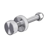
To ensure thread quality and dimensional accuracy, we recommend using plug gauges during inspection to verify external thread dimensions on screws, bolts, and other fasteners. This helps maintain high standards in threaded connections.
Additionally, selecting appropriate threading tools and inserts can help reduce costs by minimizing rework and tool replacement, especially when using replaceable insert seats for easier crash repairs.
1. Design for hole location
When designing for an internal thread location, consider the following: Is there access for a machine tool? Can chips be effectively cleared from the hole? Will there be room for attachment hardware as well as a tool (screwdriver, wrench) to drive it? How will the stress at that location affect the entire assembly? Is there enough surrounding material to support the hole without deformation?
Considerations like these are often at the heart of Design for Manufacturability (DFM) reviews, where a hole location that looks fine on a CAD design turns out to be difficult or impossible to make in real life. That’s why we always perform a careful design review of hole and thread specifications to identify potential conflicts.
2. Limit critical tolerances
Critical tolerances for hole locations should be limited to the bare minimum, and preferably no more than two. It always takes longer to hold critical tolerances at multiple locations on the same plane, and that greatly increases cost and scrap rate. In the majority of cases, critical tolerances don’t add to part quality, but they do cause avoidable production delays and rework.
Tolerances should be set to the point required for function, meeting the exact standards needed, but avoiding unnecessary precision that increases cost.
3. Control torque limits
Torque is the rotational force that applies spring tension to the threads. Too much torque doesn’t hold the part together “better”, but it does risk stripping out the threads, snapping off a screw head, or damaging the underlying material. Specify only the torque required and no more.
4. Stress distribution
Hole types and hole locations should be balanced over the entire surface area to dissipate mechanical forces evenly. Parts that are subject to periodic loading or vibration may need additional stress relief at critical locations.
5. Coarse vs. fine threads
If possible, choose a normal or coarse thread pitch. Fine threads take more time to produce and they’re easier to strip out during assembly, while not necessarily making a better finished part.
Another important consideration: similar materials in a threaded assembly will tend to gall, or ‘cold weld’ together. Galled threads can cause joint failure and require re-drilling.
Coarse threads are prefered because they have less exposed surface area and don’t gall so easily. This tendency can also be reduced by using disimilar metals in a fitting.
For both coarse and fine threads, it is important to remove any burrs from the thread crest after machining to ensure a high-quality finished thread.
Today we’ve covered the basics of machine thread terminology, common applications, engineering principles, methods of manufacture, and tips for optimizing threaded features. This information will help you to meet your development deadlines, avoid cost overruns, and hit your performance targets.
At Procision Manufacturing, we have the finest CNC turning centers and Swiss type lathes to make high precision threaded features in a variety of metals and engineering plastics.
If you found this useful and you’re ready for the next step, we’re standing by to offer a free, no obligation quotation when you upload your CAD files today.
Not yet sure if you’re design is optimized? Set up a discovery call now to talk with an engineering consultant who can help you find the right solution for your next project.
")


