

If you create part drawings, review supplier quotes, or source CNC milling services, tolerances directly affect whether your parts fit as intended, perform reliably, and stay within budget.
Tolerance decisions influence more than dimensional accuracy. They affect compatibility between mating parts, product performance, regulatory compliance, visual quality, manufacturability, inspection requirements, and overall project cost.
Every critical feature needs an appropriate tolerance, but no tolerance should be tighter than the application truly requires.
This article is for designers, engineers, and technical buyers who want to apply tolerances more effectively in their drawings, ensuring parts meet the real needs of the application without adding unnecessary cost or delay.
What is a CNC Machining Tolerance?
Tolerance is the allowable deviation from a nominal dimension or defined geometry. In other words, the drawing defines the target, and the tolerance specifies how far the finished feature may vary from that target while still meeting the design intent.
That design intent may relate to fit, motion, sealing, strength, appearance, interchangeability, regulatory requirements, or compliance with an internal or industry standard.
A part does not have to “fail completely” to be out of tolerance in a meaningful way. A feature might still appear functional in isolation but create assembly issues, cosmetic problems, excessive wear, or inconsistent performance in the finished product.
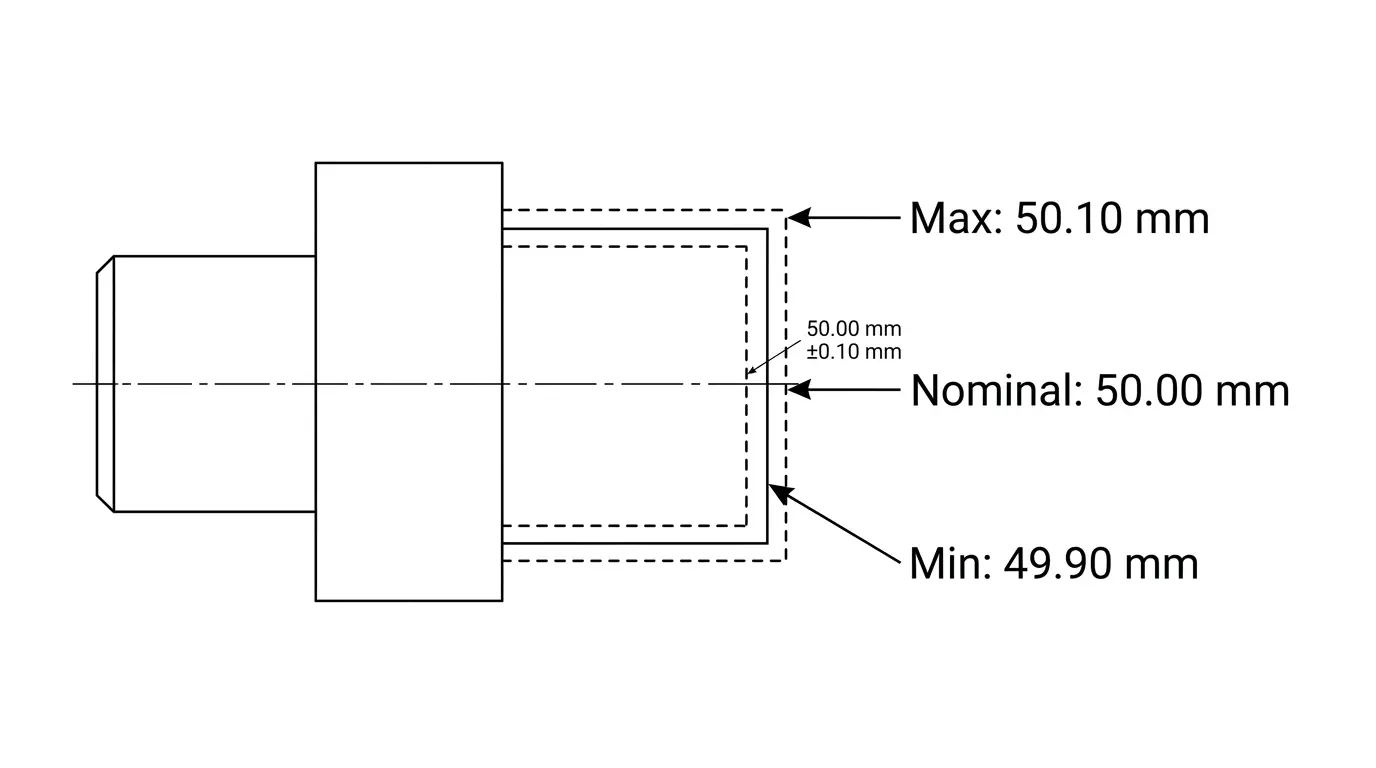
For example, one dimension might be shown as 50.00 mm ±0.10 mm. That is one common way to specify an allowable range. In that case, the acceptable size would fall between 49.90 mm and 50.10 mm. The nominal dimension is 50.00 mm, and the permitted variation is the tolerance band.
The key point is that tolerances are design requirements, not just manufacturing allowances. They exist to define what the part needs to be for the application, not to describe what a machine happens to produce.
Tight vs. Loose — What the Numbers Actually Mean
A loose tolerance gives a wider acceptable range. A tight tolerance gives a narrower one.
Neither is automatically better. The right tolerance is the one that protects the part’s function without imposing unnecessary machining difficulty, inspection burden, scrap risk, or cost.
For a simple bracket, cover, spacer, or non-critical mounting feature, a wider tolerance may be completely appropriate. For a precision locating feature, bearing fit, sealing face, or mating interface, a much tighter tolerance may be necessary.
This is where many projects go wrong. Designers sometimes assume tighter tolerances mean higher quality across the board. In practice, overly tight tolerances often add cost and lead time without improving the product.
The best-performing drawing is usually not the one with the tightest numbers across the board. It is the one that applies tighter tolerances only where they create real value.
That idea is especially important in precision CNC milling, where tolerance is always necessary, but it should never be tighter than required for the application.
The 3 Things Tolerances Directly Affect
Every tolerance decision you make on your design affects three things.
- Fit. Will your parts assemble correctly? If two mating parts are both manufactured at the outer edges of their tolerance ranges, they may not fit together at all. Tolerances ensure that even in a worst-case scenario, the parts still go together as intended.
- Function. Will the part perform as intended under real-world conditions? A shaft that’s slightly too wide won’t spin inside a bearing. A seal that’s slightly too small will leak. Tolerances define the minimum precision needed for a part to do its job.
- Cost. Tighter tolerances mean more machining time, more frequent tool changes, more advanced inspection, and a higher risk of rejected parts. Hence, it generally increases manufacturing costs, sometimes substantially. However, the exact increase depends on the process, material, feature geometry, production volume, and the degree of tolerance tightening.
How Tolerances Are Specified on Drawings
It helps to think of tolerancing not as a few isolated “types,” but as a set of systems and standard practices for clearly communicating different requirements.
Dimensional Tolerances
Dimensional tolerances define the acceptable variation on size dimensions such as length, thickness, width, diameter, or depth. The dimension establishes the intended size; the tolerance establishes the allowable variation around it.
These may be shown directly next to a dimension, or they may be covered by a general tolerance standard noted elsewhere on the drawing.
Geometric Tolerances (GD&T)
Geometric tolerancing specifies allowable variation in form, orientation, location, and runout. That includes requirements such as flatness, perpendicularity, position, concentricity, and profile. GD&T is often the better way to communicate functional requirements because it reduces ambiguity and clarifies the datum structure that matters in real assembly conditions.
For precision work, GD&T is often preferable to plus/minus dimensions alone because it better reflects how the part will be inspected and used.
Two primary standards govern GD&T practice:
- ASME Y14.5, widely used in North America
- ISO GPS (Geometrical Product Specifications) system, which is the international counterpart.
While both frameworks share the same core symbology and intent, they differ in certain rules, modifier definitions, and default interpretations, so they are not directly interchangeable.
Every drawing should clearly state which standard and revision applies (for example, ASME Y14.5-2018 or ISO 1101:2017) to ensure that the part is manufactured and inspected against the correct set of rules.
Surface Finish Tolerances
Surface finish is another specification that may be critical to performance. It does not replace dimensional or geometric tolerances, but it works alongside them. Surface roughness is commonly specified using Ra, the arithmetic average deviation of the surface profile from an ideal reference line over the evaluation length. This matters for sealing, sliding contact, wear behavior, coating adhesion, and cosmetic expectations.
For many precision CNC milling applications, a combination of dimensional tolerances, GD&T, and surface finish requirements yields the clearest results.
Standard vs. Precision vs. Ultra-Precision — Which Do You Need?
Most CNC milling projects fall into one of three tolerance tiers.
Tolerance Level | Typical Range | Best For | Relative Cost |
Standard | ±0.127mm (±0.005″) | General components, brackets, covers, non-critical features | $ |
Precision | ±0.025mm (±0.001″) | Mating features, alignment-critical parts, assemblies | $$ |
Ultra-Precision | ±0.005mm or tighter | High-risk, highly engineered applications such as medical, aerospace, optics, or specialized instrumentation | $$$ |
At Procision Manufacturing, our standard CNC milling tolerance follows ISO 2768 fine for metals and ISO 2768 medium for plastics unless otherwise specified. For high-precision requirements, we can hold tolerances as tight as ±0.025mm (±0.001″) and beyond, depending on the material, part geometry, and application.
If you’re not sure which tier you need, our engineering team will help you spec the right tolerance during the quoting process, so you’re not over-engineering or under-specifying.
What Affects Tolerance in CNC Milling?
A tolerance on a drawing is only meaningful if it is realistic for the material, geometry, and manufacturing route. Several factors influence what can be achieved consistently.
- Material Behavior: Aluminum and many steels are generally stable and predictable, while plastics may deform during cutting, clamping, or temperature change. Some materials are also more sensitive to residual stress release or humidity effects after machining.
- Part Geometry: Deep pockets, thin walls, long unsupported features, delicate ribs, and large flat areas can all increase variation.
- Tooling and Process Stability: Tool deflection, tool wear, chatter, chip evacuation, workholding, cutting strategy, and setup repeatability all affect results. Even when a tolerance is technically achievable, consistency across production depends on process control.
- Secondary Operations: Anodizing, plating, coating, heat treatment, blasting, or polishing can change the final result. If these processes affect size, geometry, or surface condition, they need to be considered before machining begins.
How to Apply Tolerances More Effectively
The most effective buyers, designers, and engineers do a few things consistently.
- They identify which features are truly critical to fit, function, safety, sealing, alignment, or compliance, and reserve tighter tolerances for those features.
- They use general tolerances for non-critical dimensions rather than imposing unnecessary precision everywhere.
- They define datums and feature relationships clearly, often using GD&T where appropriate, so the supplier understands how the part is meant to function in the assembly.
- They consider downstream processes such as coating, heat treatment, or assembly loading before finalizing tolerance values.
- They share the application context with the manufacturer.
A part for a cosmetic consumer product, a one-off prototype fixture, a medical device component, and a structural machine bracket may all require very different tolerancing strategies, even if they look similar on a screen.
What a Good CNC Milling Company Should Help You Do
A good CNC milling company should help you avoid tolerance stacking. This happens when tight tolerances are applied across multiple dimensions without considering their interactions, making a part harder to manufacture and inspect economically.
This risk increases when drawings rely on chained dimensions instead of clear datums and functional relationships. Each additional tight tolerance can increase the risk of conflict, scrap, rework, and inspection complexity, and lead to higher costs.
A capable machining partner should review your drawing, identify where tolerance stacking may be a problem, and help you apply tight tolerances only where they are functionally necessary.
Precision CNC Milling Starts With the Right Tolerance Decisions
CNC machining tolerances aren’t just numbers on a drawing. They’re design decisions that determine how well your parts work, fit, and survive in the field, and what your project costs. Understanding them puts you in control of all four.
Whether you’re a first-time buyer or an experienced engineer vetting a new CNC milling company, the right partner will make tolerances a conversation, not a guessing game.
Have a CNC milling project that requires tight tolerances? Talk to Procision Manufacturing. We’ll review your drawing, flag any tolerance concerns, and give you a transparent quote before production begins.
")


