
Key Takeaways
This article focuses on common plastic injection molding defects, what causes them, and, most importantly, how good part design prevents or controls them. Process tuning has its place, but design is where most outcomes are decided.
The most effective way to reduce scrap, tooling rework, and production delays is to address defect risk at the design and DFM stage, when changes cost nothing and impact everything. Smart design for manufacture (DFM) analysis routinely cuts tooling revisions and cycle time while improving product quality and performance.
Procision Manufacturing works with customers from the outset to identify defect risks early, propose practical geometry changes, and build molds with forgiving process windows rather than razor-thin margins.
Design Fundamentals That Affect Injection Molding Defects
Most injection molding defects can be traced back to a few design fundamentals that apply to virtually every product. When addressed correctly, molding becomes stable and repeatable. When managed poorly, defects become inevitable, no matter how skilled the processor.
The most important design considerations are:
- Wall thickness and thickness transitions
- Draft angles and feature release
- Rib and boss proportions
- Gate location and flow assumptions
- Material selection and shrink behavior
The sections below explain how these design choices directly influence defect formation.
Wall Thickness & Geometry
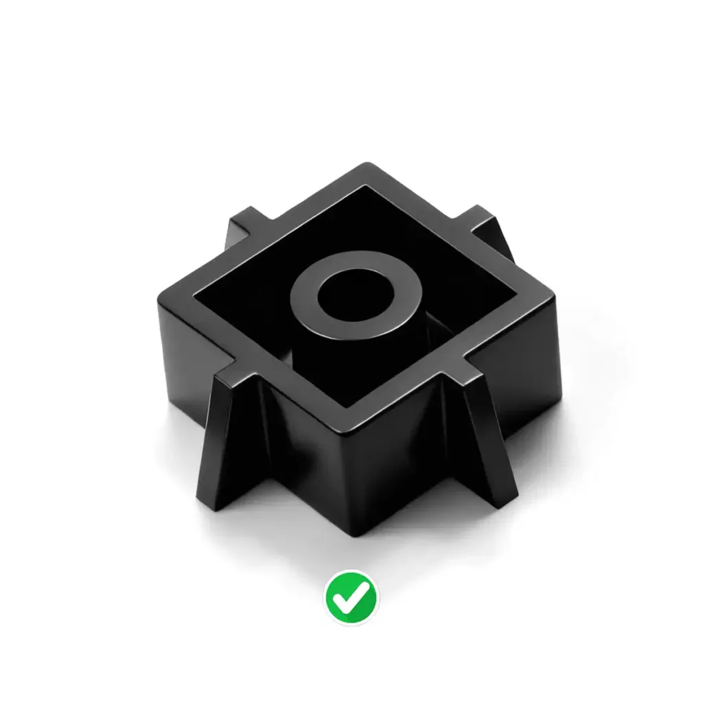
Wall thickness variation and geometry is the single most common contributor to sink marks, voids, warpage, and long cycle times. Uneven sections cool at different rates, creating internal stresses that distort parts or leave visible surface defects.
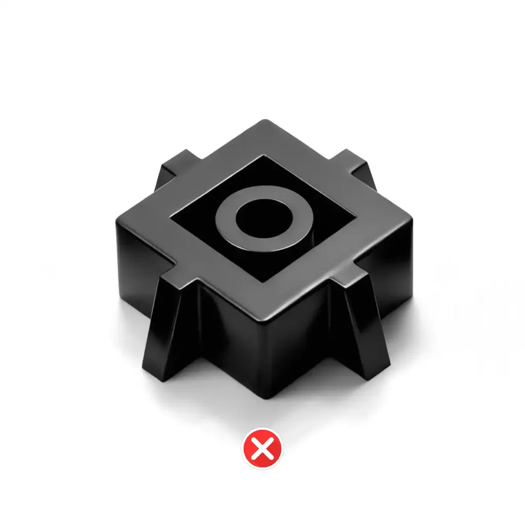
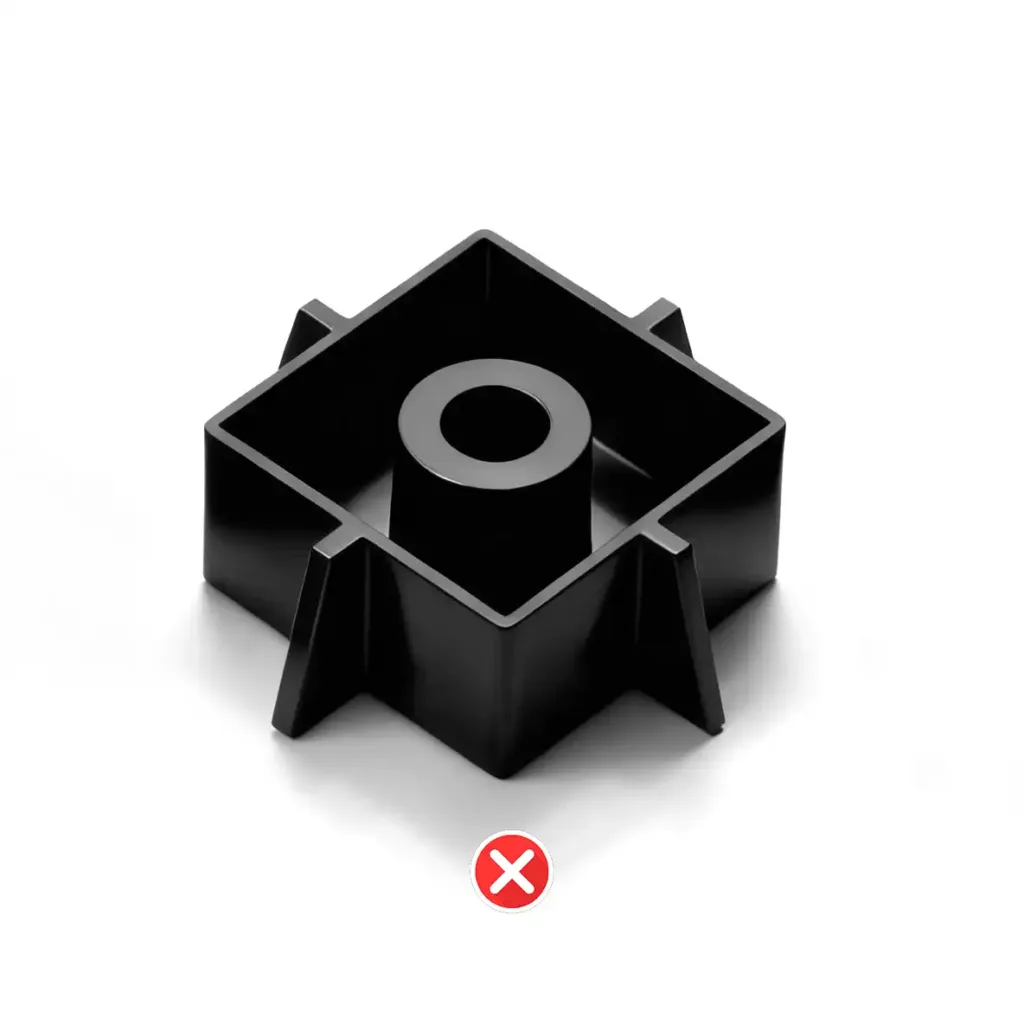
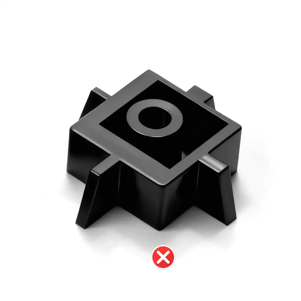
Typical nominal wall thickness ranges by material
| Material | Recommended Wall Thickness |
|---|---|
| ABS | 1.5–3.5 mm |
| Polycarbonate (PC) | 1.0–3.0 mm |
| Polypropylene (PP) | 1.0–3.0 mm |
| Nylon (PA) | 1.0–3.0 mm |
| POM (Acetal) | 1.0–3.0 mm |
Design best practices that reduce defect risk
Follow these design best practices to manage wall thickness and reduce the risk of defects.
- Keep wall thickness variation within ±10% wherever possible
- Core out thick sections instead of leaving solid masses
- Use ribs for stiffness rather than thickness for strength
- Transition between thicknesses gradually, using fillets instead of sharp steps
Sections thicker than 4~5 mm dramatically increase cooling time and are prone to sinks and voids even when tightly packed. To prevent this, use ribs and gussets to preserve stiffness while improving cooling times.
Draft Angles
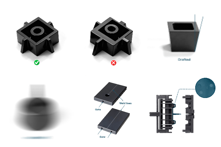
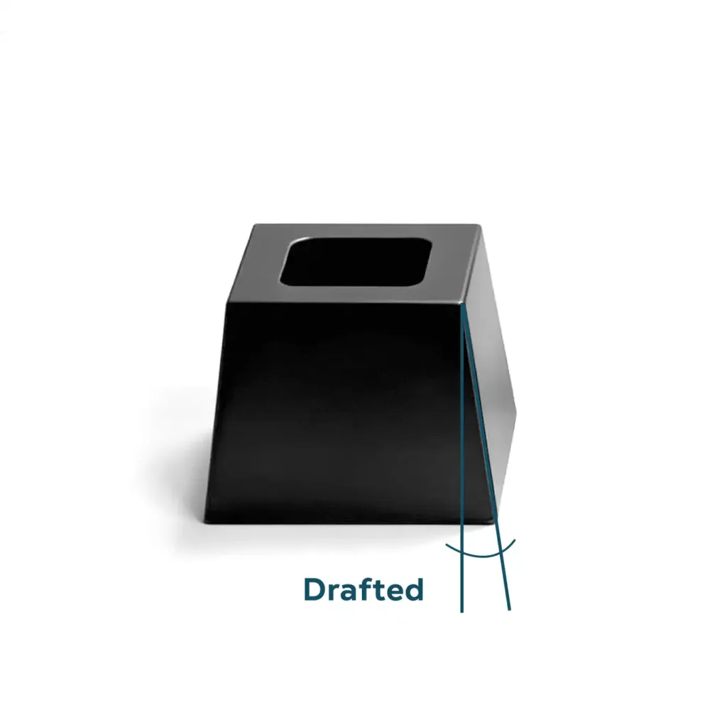
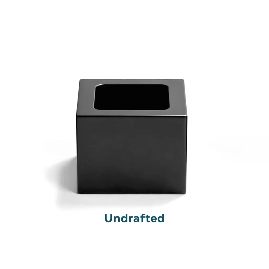
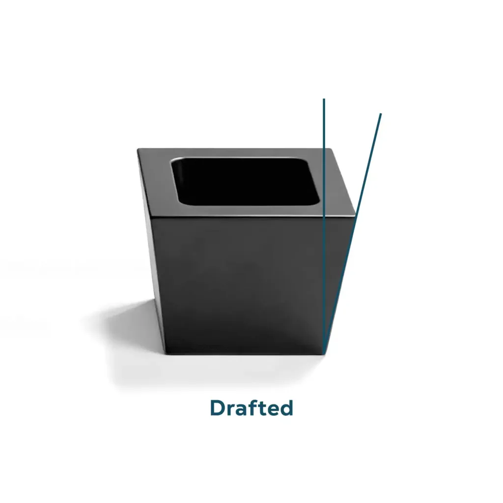
Draft angles create a clearance between the tool wall and the part feature, so it’s essential that draft is built into your design from the beginning. Although every product is unique, consider these points:
- Minimum 1° per side on smooth surfaces
- 1.5–2° or more on textured surfaces
- More draft is almost always cheaper than mold polishing or ejector tuning
Insufficient draft leads to scuffing, deformation, and visible ejection damage – problems that cannot be fixed reliably through processing alone.
Designing for Ribs
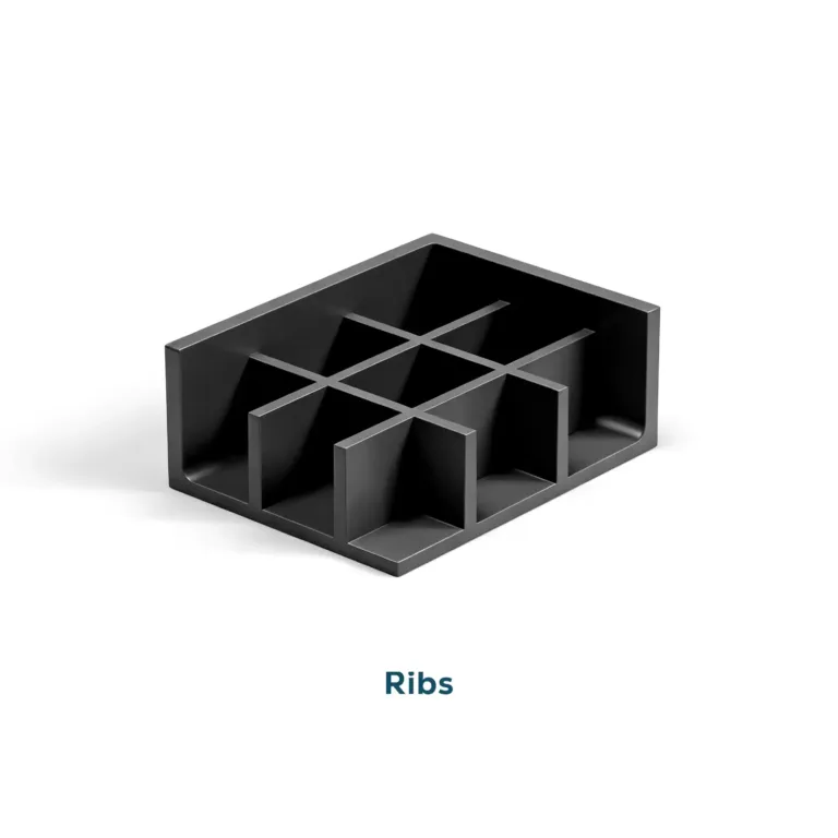
Ribs are thin, wall-like structures that usually extend perpendicular to a nominal wall. They’re used to stiffen and strengthen a wall rather than adding bulk. Here are the best practices for designing ribs:
- Thickness: 40–60% of nominal wall
- Height: typically ≤3× wall thickness
- Base fillets: generous radii to avoid stress concentration and sink
- Draft angles of 1° at minimum
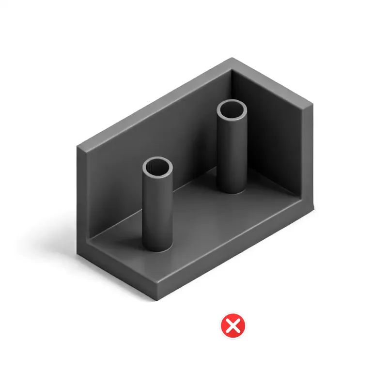
Designing for Bosses
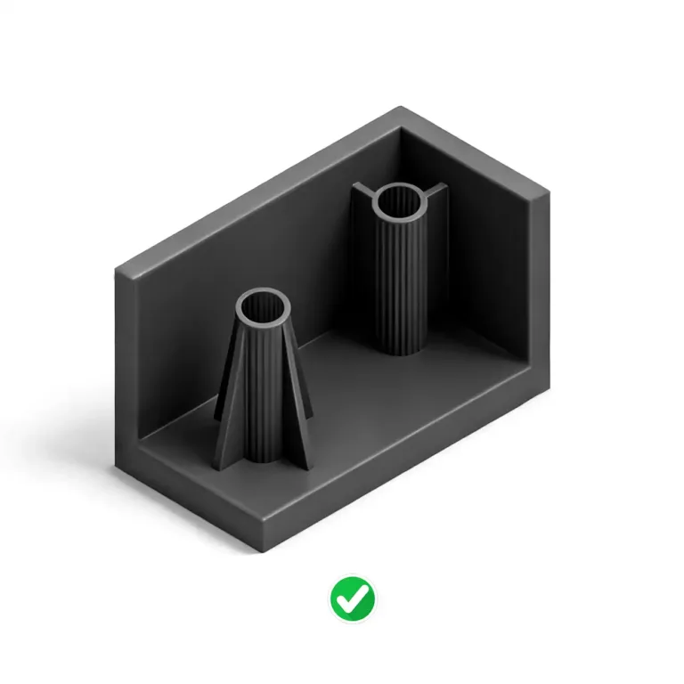
A boss is a round, vertical post that stands apart from an adjacent wall, and provides a mounting location for a screw or bolt.
- Wall thickness ~60% of surrounding wall
- Core out thick bosses
- Use supporting ribs instead of solid mass
- The external face of the boss also needs a draft of 1°
- If the boss is designed with a cored-out internal hole, this too requires a relief draft angle
These proportions prevent localized over-packing, uneven cooling and stress cracking around fasteners, all common failure points in poorly designed parts.
Gate Location, Type and Material Flow
Gate type and location strongly influence weld lines, warpage, voids, and cosmetic defects. Poor gating decisions often lead to expensive mold rework.
General design-level gating principles
It’s always a good idea to work closely with your manufacturing partner from the beginning, as they can help you choose the gate solution that best fits your product. Here are some key points to consider:
- Gate into thicker sections to support proper packing
- Avoid gating directly into thin tabs or cosmetic surfaces
- Position weld lines in non-load-bearing, non-visible areas
- Balance flow length and pressure in multi-cavity molds
General design-level gating principles
It’s always a good idea to work closely with your manufacturing partner from the beginning, as they can help you choose the gate solution that best fits your product. Here are some key points to consider:
- Gate into thicker sections to support proper packing
- Avoid gating directly into thin tabs or cosmetic surfaces
- Position weld lines in non-load-bearing, non-visible areas
- Balance flow length and pressure in multi-cavity molds
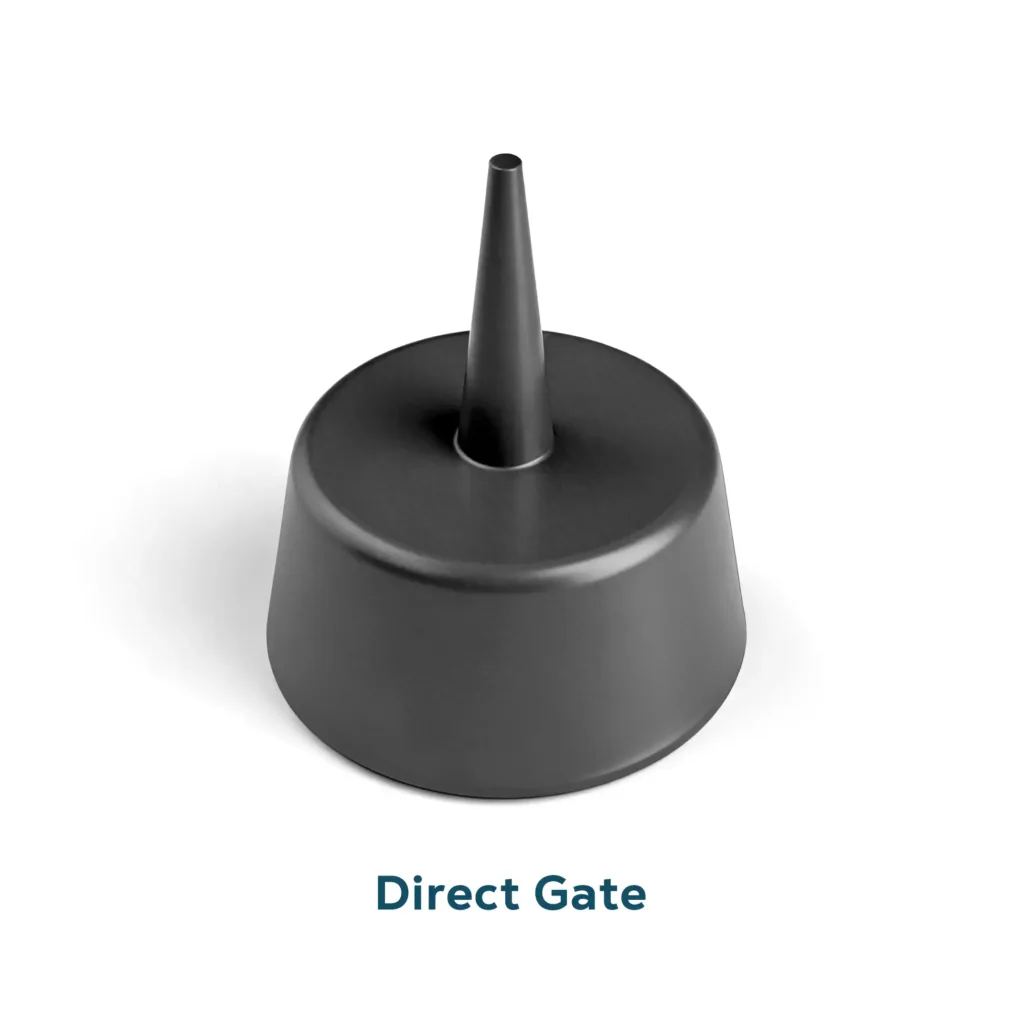
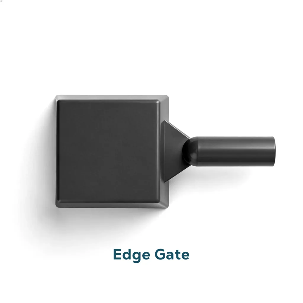
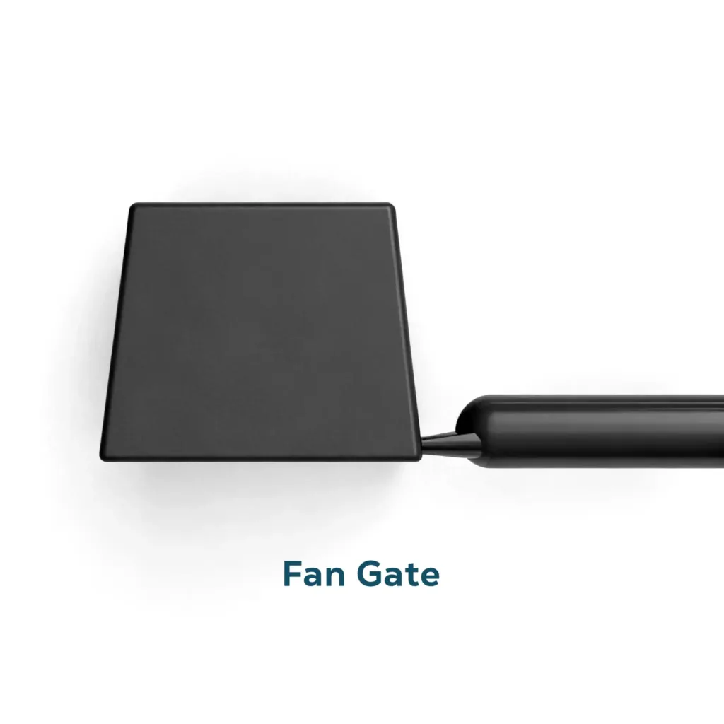
Every gate type – edge, tunnel, hot-tip and direct sprue – carries tradeoffs that must be balanced with the geometry and the part’s cosmetic requirements.
Incorrect gate placement is easy to fix in CAD and costly to correct in steel. Procision Manufacturing routinely uses flow simulation and prior experience to validate gate strategy before tooling is released.
Material Selection & Its Impact on Defects
Material choice directly affects shrinkage, warpage behavior, gate sizing, and draft requirements. Here are some general considerations based on material type.
| General Considerations | |
|---|---|
| Resins with Fillers | Resin materials that have added fillers such as fiberglass tend to shrink less but warp differently. They may need additional draft and carefully chosen gate locations to control fiber orientation. |
| Resins and Moisture | Hygroscopic materials (nylon, PC) absorb moisture from the environment, so they must be dried properly. Poor drying leads to splay, bubbles, delamination, and reduced mechanical strength, all defects that geometry alone cannot overcome. |
| Resin Adhesion | In addition, there are resins that tend to have high adhesion that causes them to stick in the mold. These include ABS, nylon, and TPU. Such resins need more draft angle and modified release strategies such as ejection pins and stripper plates. |
Book A Discovery Call
Not ready for a quote? No worries, Book a quick call with the sales rep in your area.

Sales Director Mathieu Windsor
Defect Types and Design Solutions
The following are the most common defect types that adversely affect a part’s appearance and performance. It may not be possible to completely eliminate them in all cases but they can be managed by using good design strategies.
Flow Lines, Weld Lines & Jetting
What they look like:
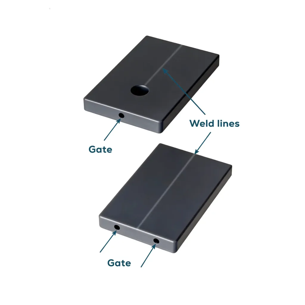
Flow lines appear as wavy streaks following melt flow. Weld lines form where two flow fronts meet, while jetting creates snake-like ripples near the gate.
Design-driven causes
- Abrupt thickness changes
- Long or unbalanced flow paths
- Poor gate placement
- Sharp internal corners
Design strategies
- Maintain uniform wall thickness
- Use radiused transitions instead of sharp corners
- Gate into thicker sections
- Control flow direction so weld lines land in non-critical areas
Texturing can hide cosmetic flow lines, but structural weld lines must be addressed at the design and gating stage since these areas can be weak and lead to potential part failure.
Sink Marks, Voids & Bubbles
What they look like:
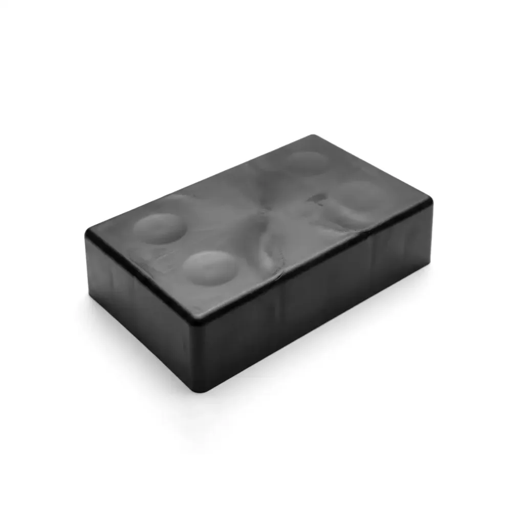
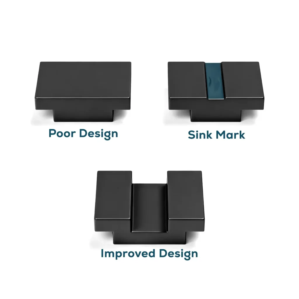
Surface depressions (sink), internal low-density pockets (voids), or trapped gas bubbles.
Design-driven causes
- Excessively thick sections
- Over-thick ribs or bosses
- Poor thickness transitions
Design strategies
- Core out thick sections
- Keep ribs and bosses at 40–60% of wall thickness
- Maintain gradual cross-section transitions
- Avoid sharp internal corners
Packing pressure can reduce sink, but geometry ultimately controls whether consistent results are achievable.
Warpage & Dimensional Instability
What it looks like: Twisting, bowing, or curling after ejection.
Design-driven causes
- Uneven wall thickness
- Asymmetric feature layouts
- Fiber orientation in filled materials
Design strategies
- Maintain uniform wall thickness
- Balance ribs and features symmetrically
- Avoid large unsupported flat areas
- Design stiffness into geometry rather than thickness
Correcting warpage after tooling often requires costly mold modifications. Early DFM and flow analysis are far cheaper.
Discoloration, Burn Marks & Delamination
What they look like: Darkened areas, color streaking, charred spots, or flaky surface layers.
Design driven causes
- Trapped air at flow ends
- Excessive residence time
- Material contamination or moisture
Design strategies
- Provide adequate venting paths
- Avoid dead-end flow regions
- Use compatible materials and colorants
- Enforce proper material handling and drying
Ready to start your plastic injection molding project?
Upload your drawings for a free quotation from Procision Manufacturing.
Short Shots, Flash & Ejection Marks
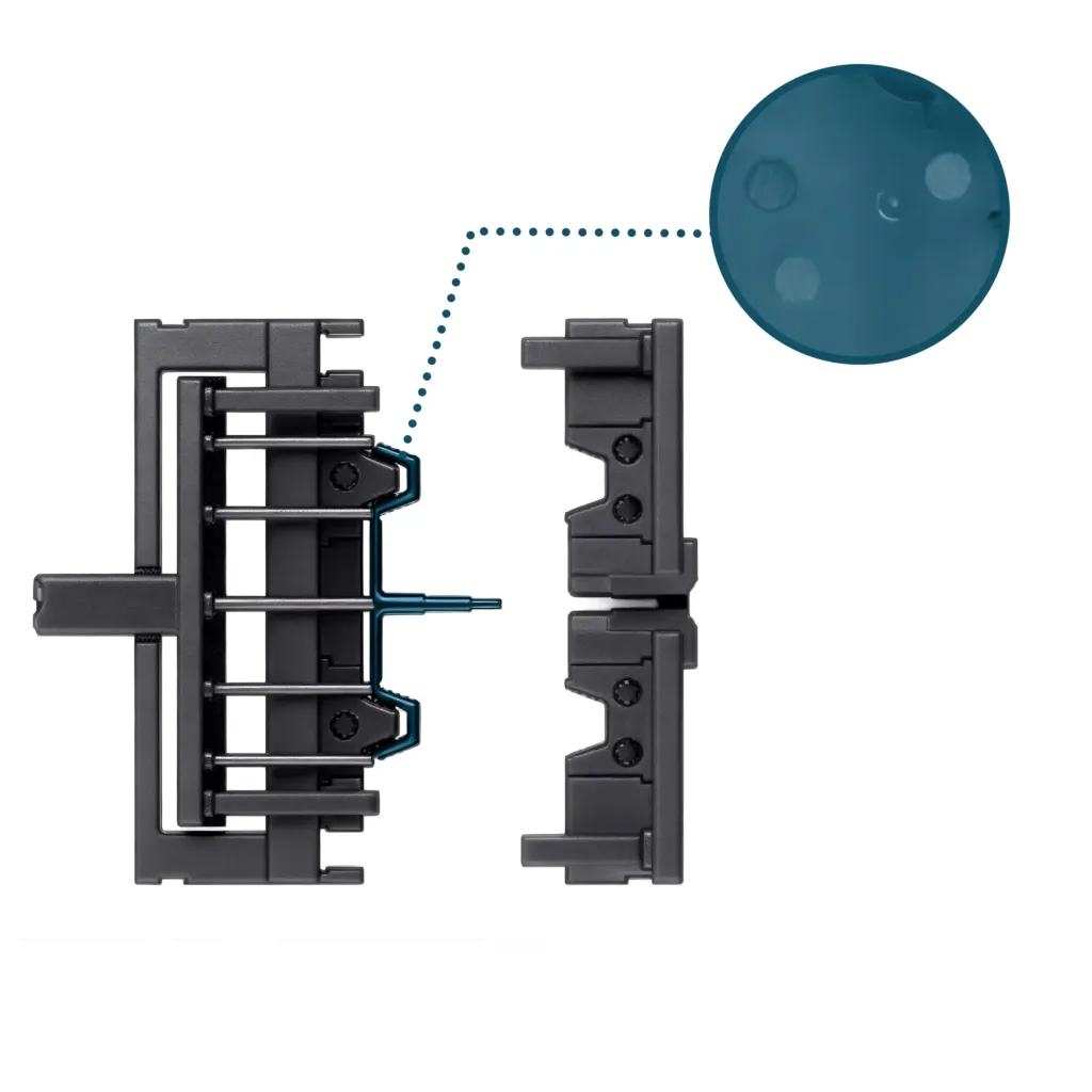
Short shots are responsible for making a part that is incomplete, with unfinished features. Flash is thin, paper-like webbing that radiates laterally from the part’s surface and must therefore be trimmed off. Ejection marks are indentations or dimples on the cavity or underside of the part created by the ejector pins.
Design-driven causes of short shots
- Insufficient injection pressure
- Poor gate location
Design strategies for short shots
- Thicken the flow area
- Add or move gates
- Improve venting
Design-driven causes of flash
- Excess injection pressure
- Misplaced parting line
Design strategies for flash
- Reorient location of parting line relative to gates/runners
- Add additional gates to disperse pressure
Design-driven causes of ejector pin marks
- Ejector pins too small
- Ejection area too small / thin
- Uneven pins / uneven distribution
Design strategies for ejector pin marks
- Increase pin diameter
- Increase pin draft angle
- Distribute ejector pins over larger surface area
- Reorient pin locations to stronger areas
Ejector pin marks may be unavoidable but their placement can be optimized so they don’t interfere with part function or appearance.
Good DFM Reduces Cost and Production Lead Time
Every defect prevented at the design stage saves time and money downstream.
Real-world outcomes from Procision DFM reviews include:
- Reduced cycle time through optimized wall thickness
- Eliminated side-actions via feature redesign
- Part consolidation that removes fasteners and assembly steps
- Gate relocations that prevent cosmetic rework
Design changes cost nothing in CAD. Tooling changes require re-cutting steel, re-sampling, and weeks of delay.
Why Work with Procision Manufacturing?
Procision combines design review, tooling, and production under one roof so intent, execution, and outcome stay aligned.
- Early CAD-stage defect identification
- Practical geometry recommendations
- Experience with demanding materials and tight tolerances
- Stable, repeatable production processes
The result is fewer tooling iterations, faster qualification, and parts that work the first time.
Ready to eliminate defect risk on your next plastic injection molding project? Submit your CAD files to Procision for a no-obligation DFM review and identify issues before they turn into scrap, delays, or rework.
Precision starts with collaboration
Upload your CAD files for a quotation and DFM review.