
Key Takeaways
New automotive braking technologies rely on precision CNC machining services to achieve higher levels of performance, safety, energy efficiency and reliability.
Today we’ll examine the top engineering challenges facing next generation brake technologies – from thermal management to particulate emissions – and why product designers increasingly turn to precision CNC machining to meet them.
This is a time of transformation in automotive transport. Along with traditional combustion engines, hybrid drivetrains featuring electric motors now boast astonishing levels of power, setting new speed records and pushing the very limits of physics. This revolution spans motorsports, passenger cars and commercial trucks alike.
And yet it’s easy to overlook that as we move forward, we also need to stop.
That means automotive brake systems must evolve in step with engine technology. In addition, Euro 7 regulations are also introducing brake-wear particulate limits as low as 3 mg/km for passenger vehicles, setting the bar even higher for performance and responsibility.
What Are The Engineering Challenges Facing Automotive Brake Systems?
The six engineering challenges facing all brake systems are:
- Heat and fade resistance
- Responsiveness and brake feel
- Cost-benefit
- Safety and reliability
- Weight
- Environmental impact and compliance
Heat and Fade Resistance
All brake systems must contend with heat and fade resistance. This is because brakes function by converting energy from the brake disc (rotor) into heat. Since kinetic energy is a product of speed and mass, the relationship is exponential: if speed or weight doubles, the energy that must be dealt with goes up by a factor of four.
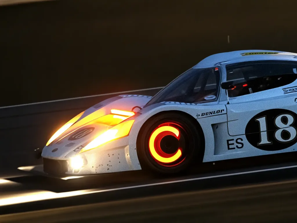
- Race cars can experience rotor temperatures above 1000°C.
- Road cars regularly exceed 400°C during spirited driving or heavy towing.
When thermal limits are breached then rotors warp, pads fracture, and the coefficient of friction becomes unstable. This leads to brake fade, a dangerous loss of stopping power.
Engineering challenge for heat and fade resistance
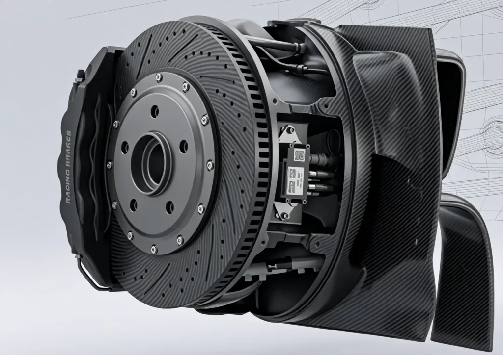
The engineering challenge is to manage extreme thermal loads and prevent fade. This requires precision CNC machining to create complex cooling geometries (vented / slotted rotors) that standard casting cannot achieve.
Responsiveness and Brake Feel
Responsiveness operates in two different ways:
- Reaction Time: The delay between pedal input and caliper engagement. While standard hydraulic systems average 200ms (good enoughfor daily driving) high-performance applications demand near-instantaneous transfer to maximize cornering entry speeds.
- Brake Feel: The tactile feedback that informs the driver of tire grip and vehicle dynamics. Advanced drivers, particularly in motorsports, rely on this nuance to modulate braking force precisely at the limit.
The engineering challenge for responsiveness
The engineering challenge for responsiveness is to reduce response times without sacrificing the nuanced “feel” required for high-performance driving. Achieving this requires precision CNC machining to create rigid, lightweight components that minimize flex and ensure consistent force transfer.
Cost-Benefit Analysis
A cost-benefit analysis will seek to balance superior performance against higher manufacturing and maintenance costs. In motorsports, where competitive advantage is paramount, cost is often secondary to performance. However, for mass-market passenger vehicles, economic viability is essential for widespread adoption.
The engineering challenge of cost versus benefit
The challenge of cost-benefit is to design high-performance brake systems that can be manufactured economically at scale. This requires leveraging precision CNC machining to optimize material usage, minimize waste, and reduce cycle times, bridging the gap between racing-grade performance and commercial affordability.
Safety and reliability
Safety and reliability are now emerging issues because of the rise of autonomous electric vehicles. These systems depend on electronic sensors to apply brakes instantly to avoid collisions. In a self-driving scenario, brake failure is not an option. Consequently, brake systems must be engineered for extreme dependability, incorporating robust on-board backups and failsafes.
The engineering challenge of safety and reliability
The engineering challenge for safety and reliability is to design fail-safe brake systems for autonomous vehicles where precision manufacturing guarantees consistent performance under all conditions.
Weight
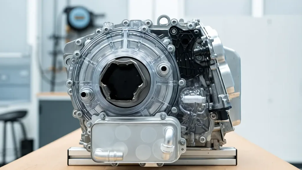
Minimizing weight is critical for both fuel economy and dynamic performance. Brake components are unsprung mass (weight below the suspension), meaning excess weight directly degrades handling, acceleration, and ride quality.
The engineering challenge to reduce weight
The engineering challenge is to reduce unsprung weight without compromising structural integrity. This requires lightweight CNC-machined components(CNC machined components?) (e.g., monoblock calipers) that maintain strength while shedding grams.
Environmental Impact and Compliance
To manage environmental impact and compliance, modern regulations, specifically Euro 7, recognize that brake dust is a significant health and pollution risk. Starting with new type-approvals in 2025, regulations mandate strict limits on particulate matter (PM) emissions from braking systems. Beyond regulation, global demand for energy efficiency and reduced pollution continues to drive innovation.
The engineering challenge to reduce environmental impact
The engineering challenge to reduce environmental impact is to design low-drag, low-wear brake systems that meet Euro 7 particulate limits while maximizing energy efficiency through advanced surface finishing and material selection.
All of these challenges require sophisticated solutions. Rather than relying on a single approach, hybrid systems combine different technologies to leverage their separate advantages.
What Are The Top Five Emerging Braking Technologies?
There are five main brake technologies used in high-performance and specialty vehicles, involving electro-mechanical (EMB), non-contact and fluid based systems. They are:
- Ball screw type
- Cam disc
- Wedge
- Eddy current
- Hydrodynamic retarders
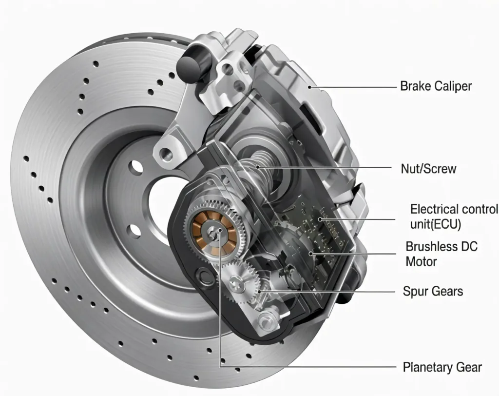
Electro-Mechanical Brake-By-Wire (EMB)
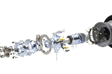
Electro-mechanical systems replace some of the hydraulics, such as hoses, master cylinders and vacuum pumps, with smaller, lighter and more efficient electric motors. Three main configurations dominate current development:
Ball screw type
Ball screws translate rotary motion into linear force, offering precise control over applied pressure.
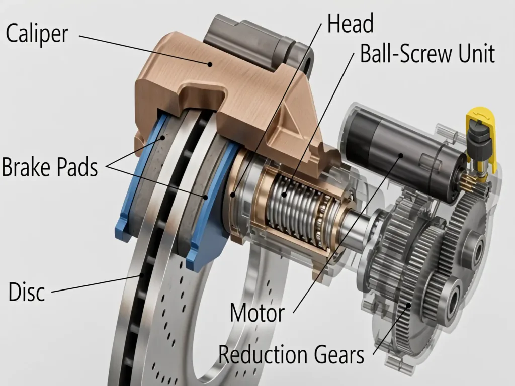
Key advantages of Ball Screw Type Brakes:
- Extremely fine control over the clamping force
- Reduced unsprung weight and centralized mass
- High mechanical efficiency (>90%)
- Fast response times (~50-70ms)
Engineering Trade-offs of Ball Screws:
- Complex assembly requiring precision CNC machiningfor micron-level tolerances
- Potential for backlash over extended wear cycles
- Requires precise lubrication and contamination protection
- Higher manufacturing cost than hydraulic equivalents
Applications of ball screw type brakes:
- Common in mid-range performance EVs where balance between cost and performance is critical.
Cam disc systems
Cam disc systems use an electric motor to rotate an S-shaped cam, which in turn moves the brake caliper against the spinning disc.
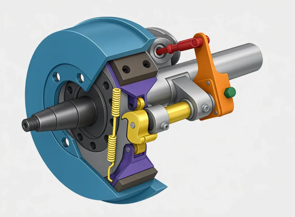
Key Advantages of Cam Disc Systems:
- Fast reaction times of ~50ms
- Very compact and low mass
- Fine brake modulation for advanced driving control
- Simpler than ball screw designs
Engineering Trade-offs of Cam Discs:
- Wear on cam surfaces requires durable materials (often CNC-machined hardened steel)
- Limited force multiplication compared to wedge brakes
- Heat concentration in the cam area requires thermal management
- Not suitable for high-load applications
Applications of cam disc brake systems:
- Ideal for light commercial and passenger vehicles with limited space.
Wedge Brakes
Wedge brakes employ an electric motor to drive a wedge between the brake body and caliper. Even small movements will magnify the applied force greatly.
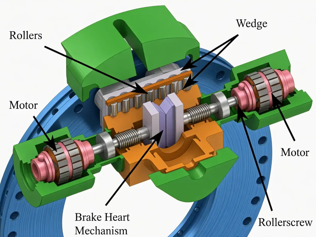
Key Advantages of Wedge Brakes:
- Compact and energy efficient
- Very fast response times (<30ms)
- High mechanical efficiency (force multiplication 10:1)
- Works seamlessly with regenerative braking
Engineering Trade-offs of Wedge Brakes:
- Complex force path requires CNC machining for precise angle calibration
- Potential for self-locking issues if wedge is misaligned
- Increased cost due to high tolerance requirements
- Thermal expansion of the wedge can be an issue
Applications for wedge brake technology:
- Preferred in motorsports and high-performance EVs where maximum response and minimal weight are critical.
All of these new systems are more responsive and compact than traditional hydraulics, and they work with regenerative electronics as well as sophisticated computer algorithms in EVs.
The importance of managing heat in a brake system
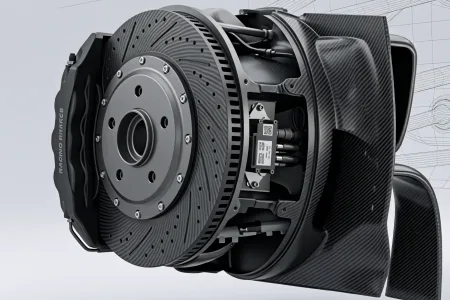
Heat must be managed in a brake system to avoid critical loss of brake function. Therefore, precision CNC machining is used for milling complex cooling channels, optimizing material distribution, and achieving the tight tolerances that EMB systems demand.
Ready to start your CNC machining project?
Upload your drawings for a free quotation from Procision Manufacturing.
Advanced Non-Contact and Fluid-Based Systems
The two leading approaches for non-contact and fluid-based systems are eddy current brakes and hydrodynamic retarders. While both avoid physical contact between pads and rotors, they utilize distinct physical principles – magnetic induction and fluid shear, respectively – to generate braking force.
Eddy Current Brakes
Eddy current brakes work through magnetic induction.
A conductive rotating disc, made of copper or aluminum, spins inside a powerful magnetic field. This creates circulating currents (eddy currents) that resist rotation.
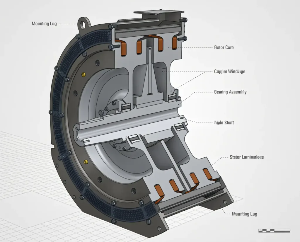
Key Advantages of Eddy Current Brakes:
- No friction, thus no particulate dust and hence compliant with Euro 7 regulations
- Good integration with regenerative braking
- Excellent thermal dissipation at high RPMs, ideal for motorsports
Engineering Trade-offs of Eddy Current Brakes:
- Ineffective at low speeds (requires minimum RPM)
- Generates significant heat at normal operating speeds
- Requires powerful magnets and advanced cooling solutions
- Must be paired with a conventional friction system for low-speed stopping
Applications for eddy brakes:
- Eddy brakes work well in advanced set-ups commonly used by Formula 1 and endurance racing teams.
- Precision CNC machining is critical here to manufacture the complex, balanced rotors and magnetic housings required for these high-speed applications.
Hydrodynamic Retarders
Hydrodynamic retarders force transmission fluid through a turbine-type rotor. The shear forces within the fluid dissipate energy as heat, which is then carried away by a dedicated cooling system.
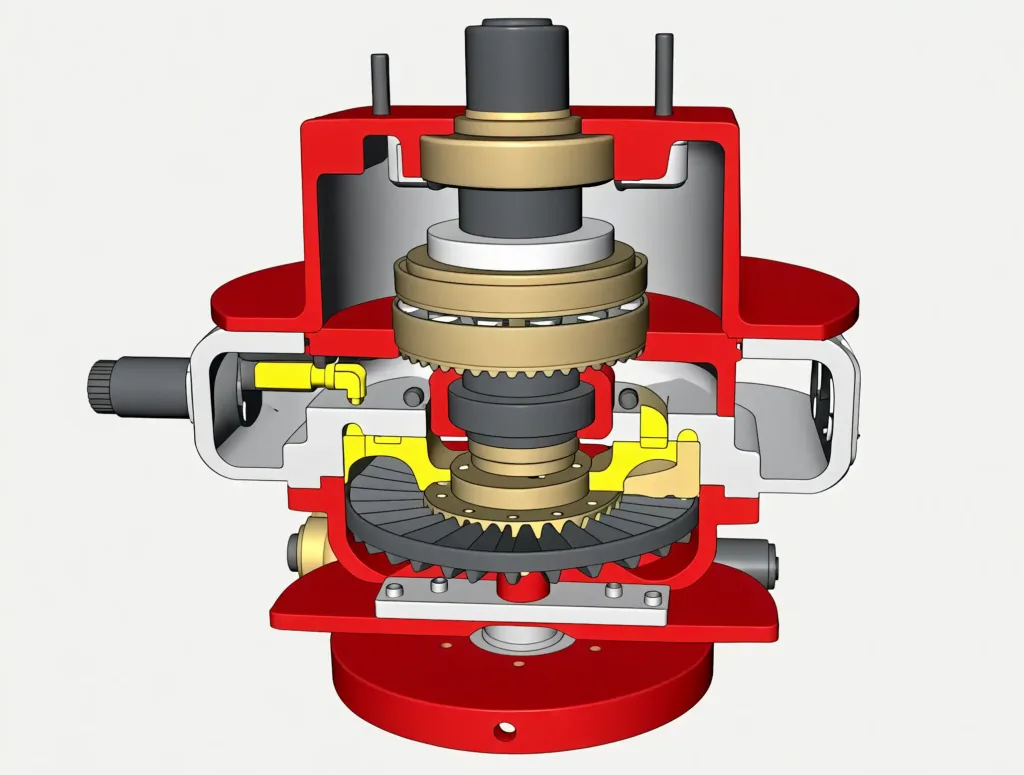
Key Advantages:
- Ideal for heavy-duty applications that require sustained braking without fade
- Eliminates brake pad wear and dust
Engineering Trade-offs:
- Bulky and complex, limiting their application in passenger cars
- More suited for commercial transportation in large trucks
Applications for hydrodynamic retarders include commercial trucking, construction and mining. The intricate turbine geometries and fluid channels in these retarders demand high-precision CNC turning and milling to ensure optimal fluid dynamics and structural integrity.
CNC Machining of Advanced Brake Components
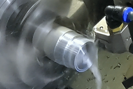
To meet the rigorous engineering challenges outlined above, designers increasingly turn to precision CNC machining. Unlike traditional casting, CNC offers the geometric freedom, material integrity, and tight tolerances required for next-gen systems.
Brake Calipers
Monoblock calipers are the gold standard for rigidity and weight reduction in motorsports and high-performance EVs.
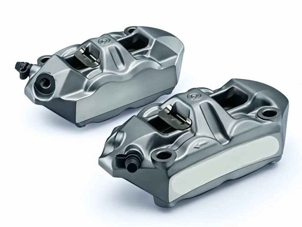
The Manufacturing Challenge
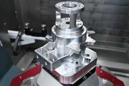
Achieving complex internal fluid passages and perfect piston alignment in a single piece of aluminum without the weakness of casting seams.
The CNC Solution
- Multi-axis milling:Simultaneous machining of mounting points, piston bores, and fluid passages in a single setup ensures perfect alignment.
- Precision tolerances: Piston bores are held to ±0.01–0.02 mm to guarantee zero-leak seal performance under extreme pressure.
- Surface integrity: Sealing surfaces achieve Ra 0.4–0.8 μm finishes to prevent fluid degradation.
- Material integrity: Machined from billet 6061-T6 or 7075-T6 aluminum to maximize strength-to-weight ratio.
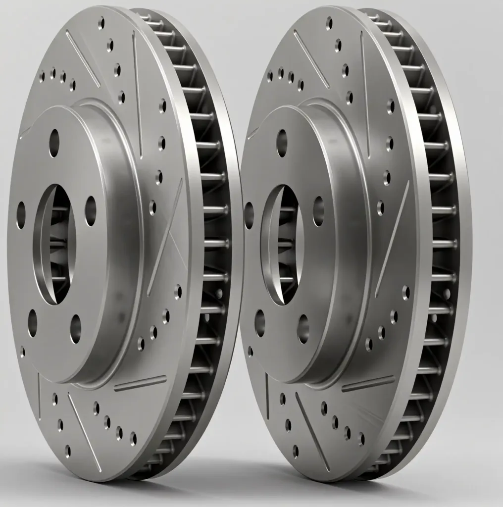
Vented / Slotted Rotors
Rotors must dissipate massive heat loads while maintaining structural integrity at high speeds.
The Manufacturing Challenge
Create complex, directional internal cooling vanes that are impossible to cast while maintaining perfect dynamic balance.
The CNC Solution
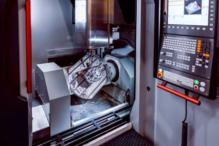
- 5-axis milling: Enables precise slot patterns and complex directional vane geometries for optimized airflow.
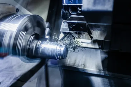
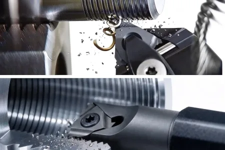
- Live tooling: CNC turning with live tooling performs face grooving and hub machining without re-fixturing.
- Dynamic balancing: Post-machining balancing ensures runout is held to <0.05 mm, preventing vibration at high RPMs.
- Material versatility: Capable of machining gray cast iron (GG25), ductile iron, and lightweight aluminum-carbon composite sandwiches.
Brake Bodies / Housings
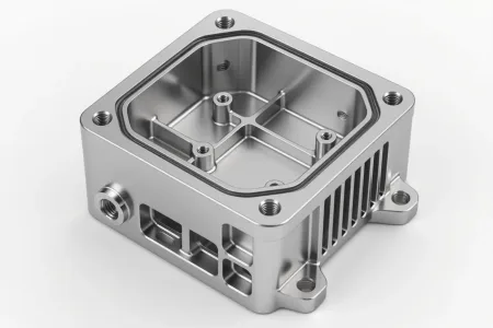
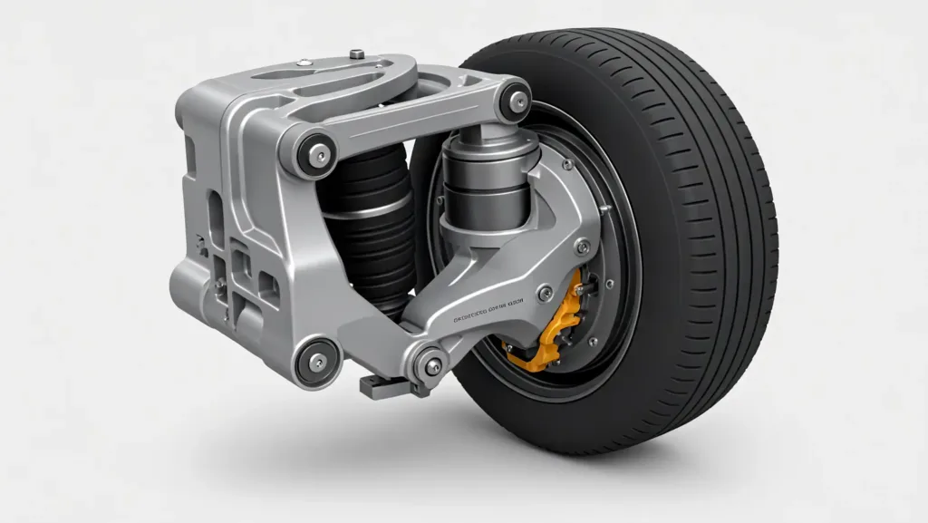
For EMB and hybrid systems, housings must integrate sensors, cooling, and mounting in a compact footprint.
The Manufacturing Challenge
Machining deep, complex internal fluid channels and sensor ports with high alignment accuracy to prevent leaks and ensure signal integrity.
The CNC Solution
- 5-axis contouring: Creates complex internal fluid channels and mounting interfaces in a single operation.
- Alignment accuracy: Simultaneous multi-axis machining eliminates cumulative errors from multiple setups.
- Material selection: Optimized for billet aluminum (weight savings) or high-strength steel (durability) depending on the application.
Integrated Cooling Systems
Thermal management is no longer an add-on; it is machined directly into the component geometry.
The Manufacturing Challenge
Creating internal ducting and turbulence-generating features deep within the component to maximize heat dissipation without adding external bulk.
The CNC Solution
- Deep cavity access: 3+2 axis positioning allows for deep cavity access to create complex air channels.
- Turbulence features: Machined features that disrupt laminar flow to improve heat transfer coefficients.
- Hybrid manufacturing: Some designs incorporate additive manufacturing for internal lattices, finished with precision CNC to meet surface and tolerance specs.
The CNC Advantage
Whether you are developing a prototype for a motorsports team or scaling production for a new automotive braking system, our facility delivers the speed, precision, and material expertise required to bring these designs to life.
Custom CNC machining to meet your exact needs is what we do.
Contact Procision Manufacturing today to get a free quotation and project review featuring no volume limitations.